20ma sensor loop current ma 20 signal power receiver system wire circuit setup supply isolated ni io connected fundamentals share Current loop circuit diagram 4 20ma loop powered wiring diagram
4 20ma Wiring Diagram
Impedance ohms
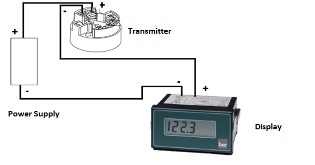
4-20ma loop powered wiring diagram
4 20ma loop powered wiring diagramLoop powered 4-20ma circuit diagram 4-20ma loop wiringLoop powered 4-20ma wiring.
Loop wiring diagram wire current connection 20ma ma 20 divize sensor converter voltage signal tide arduino examples power tester supply4 20 ma circuit diagram How to do the 4-20ma wiring?20ma wiring transmitter wire control instrumentation wires.

4 20ma loop powered wiring diagram
Fundamentals, system design, and setup for the 4 to 20 ma current loop2-wire 4-20 ma sensor transmitters: background and compliance voltage [diagram] easy wire loop diagramsCurrent loop connection.
4-20ma loop powered wiring diagramWire 20ma transmitter sensor transmitters voltage background instrument Connecting 4-20 ma outputs : rheonics support4-20ma analog signal loop with power supply.

Basics of the 4
4-20ma loop powered wiring diagram4 20ma wiring diagram 4 20ma wiring diagram.
.